


| Dimensions (H.W.D.), mm | |
|---|---|
| Number of transformers | |
| Transformer rated voltage MV/LV, kV | |
| Transformer rated voltage MV/LV, kV | |
| Rated frequency: | 50Hz |
| Degree of protection: | |
| Altitude above sea level: | |
| Ambient temperature: | |
| Relative humidity: | ≤ 100% (at +25°C) |
| Ventilation: | Passive (natural convection) / Active (mechanical forced ventilation) |
| Standards: | LST EN 62271-202 |
| 10 kV section | — |
| 10 kV Maximum voltage: | 12 kV |
| 10 kV Test voltage (50Hz, 1 min): | 28 kV |
| 10 kV Rated frequency: | 50 Hz |
| 10 kV Impulse test voltage (1.2/50 μs): | 75 kV |
| 10 kV switchgear compartment maintenance: | External |
| 10 kV Switchgear insulation: | Air insulation |
| 10 kV Network neutral: | Isolated |
| 10 kV Degree of protection: | IP3X |
| 10 kV Service category: | LSC2A |
| 10 kV Disconnectors | According to AB 'ESO' technical requirements |
| 10 kV Surge arresters | According to AB 'ESO' technical requirements |
| 0.4 kV section | — |
| 0.4 kV rated busbar current | ≥1900 A |
| 0.4 kV busbar rated peak withstand current | 40 kA |
| Maintenance of 0.4 kV section: | Vienpusis – išorinis |
| 0.4 kV rated insulation voltage | 690 V |
Basic Information
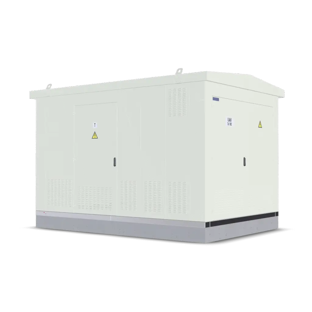
Enclosure:
The substation consists of a reinforced concrete foundation and a metal enclosure with a removable roof. The substation is divided into three sections separated by partitions: 10 kV compartment, power transformer compartment, 0.4 kV compartment.
Additional information
Medium voltage:
To be equipped with hermetically sealed air-insulated medium-voltage switchgear; space for an RTU provided.
Transformer:
Prepared space with an oil collection pit for a three-phase hermetic oil transformer; (≤1600x1100x1800) up to 1000 kVA.
Low voltage:
Incoming fuse-switch block; Space for control metering; Space for commercial metering (KAS); Designated space for up to 8 linear fuse-switch blocks; Aluminum (Al) or Copper (Cu) busbars with pressed-in bushings (for convenient mounting of fuse-switch blocks); Auxiliary panel (SRS).
Grounding conductors:
Transformer construction: 10 mm²; Doors: 4 mm².
Internal use panel
Plug socket ~230V with grounding contacts, protected by RCCB and 1-phase C16A circuit breaker; 1-phase C6A circuit breaker for protection of 10 kV short-circuit indicator power supply; 1-phase C6A circuit breaker for lighting protection.
Verification metering
One location (three-phase) is allocated for the control electrical metering device and test terminal in the 0.4 kV distribution equipment compartment; upon order, current transformers are installed and connected.
Equipment details:
The power transformer is loaded from the top by removing the roof. The transformer is placed on wheels into designated fixed positions that prevent movement. MV – Medium Voltage compartment with equipment; LV – Low Voltage compartment with equipment; KAS – Commercial metering.
MT-10/0.4-1 X 1000
Designed for receiving 10 kV, 50 Hz electrical power and transforming it to 0.4 kV voltage for distribution to users; this is an outdoor service transformer substation connected to external networks via underground cables.
| Dimensions (H.W.D.), mm | |
|---|---|
| Number of transformers | |
| Transformer rated voltage MV/LV, kV | |
| Transformer rated voltage MV/LV, kV | |
| Rated frequency: | 50Hz |
| Degree of protection: | |
| Altitude above sea level: | |
| Ambient temperature: | |
| Relative humidity: | ≤ 100% (at +25°C) |
| Ventilation: | Passive (natural convection) / Active (mechanical forced ventilation) |
| Standards: | LST EN 62271-202 |
| 10 kV section | — |
| 10 kV Maximum voltage: | 12 kV |
| 10 kV Test voltage (50Hz, 1 min): | 28 kV |
| 10 kV Rated frequency: | 50 Hz |
| 10 kV Impulse test voltage (1.2/50 μs): | 75 kV |
| 10 kV switchgear compartment maintenance: | External |
| 10 kV Switchgear insulation: | Air insulation |
| 10 kV Network neutral: | Isolated |
| 10 kV Degree of protection: | IP3X |
| 10 kV Service category: | LSC2A |
| 10 kV Disconnectors | According to AB 'ESO' technical requirements |
| 10 kV Surge arresters | According to AB 'ESO' technical requirements |
| 0.4 kV section | — |
| 0.4 kV rated busbar current | ≥1900 A |
| 0.4 kV busbar rated peak withstand current | 40 kA |
| Maintenance of 0.4 kV section: | Vienpusis – išorinis |
| 0.4 kV rated insulation voltage | 690 V |
Optional accessories


MT-10/0.4-1 X 1000
| Dimensions (H.W.D.), mm | |
|---|---|
| Number of transformers | |
| Transformer rated voltage MV/LV, kV | |
| Transformer rated voltage MV/LV, kV | |
| Rated frequency: | 50Hz |
| Degree of protection: | |
| Altitude above sea level: | |
| Ambient temperature: | |
| Relative humidity: | ≤ 100% (at +25°C) |
| Ventilation: | Passive (natural convection) / Active (mechanical forced ventilation) |
| Standards: | LST EN 62271-202 |
| 10 kV section | — |
| 10 kV Maximum voltage: | 12 kV |
| 10 kV Test voltage (50Hz, 1 min): | 28 kV |
| 10 kV Rated frequency: | 50 Hz |
| 10 kV Impulse test voltage (1.2/50 μs): | 75 kV |
| 10 kV switchgear compartment maintenance: | External |
| 10 kV Switchgear insulation: | Air insulation |
| 10 kV Network neutral: | Isolated |
| 10 kV Degree of protection: | IP3X |
| 10 kV Service category: | LSC2A |
| 10 kV Disconnectors | According to AB 'ESO' technical requirements |
| 10 kV Surge arresters | According to AB 'ESO' technical requirements |
| 0.4 kV section | — |
| 0.4 kV rated busbar current | ≥1900 A |
| 0.4 kV busbar rated peak withstand current | 40 kA |
| Maintenance of 0.4 kV section: | Vienpusis – išorinis |
| 0.4 kV rated insulation voltage | 690 V |
Basic Information
Enclosure:
The substation consists of a reinforced concrete foundation and a metal enclosure with a removable roof. The substation is divided into three sections separated by partitions: 10 kV compartment, power transformer compartment, 0.4 kV compartment.
Additional information
Medium voltage:
To be equipped with hermetically sealed air-insulated medium-voltage switchgear; space for an RTU provided.
Transformer:
Prepared space with an oil collection pit for a three-phase hermetic oil transformer; (≤1600x1100x1800) up to 1000 kVA.
Low voltage:
Incoming fuse-switch block; Space for control metering; Space for commercial metering (KAS); Designated space for up to 8 linear fuse-switch blocks; Aluminum (Al) or Copper (Cu) busbars with pressed-in bushings (for convenient mounting of fuse-switch blocks); Auxiliary panel (SRS).
Grounding conductors:
Transformer construction: 10 mm²; Doors: 4 mm².
Internal use panel
Plug socket ~230V with grounding contacts, protected by RCCB and 1-phase C16A circuit breaker; 1-phase C6A circuit breaker for protection of 10 kV short-circuit indicator power supply; 1-phase C6A circuit breaker for lighting protection.
Verification metering
One location (three-phase) is allocated for the control electrical metering device and test terminal in the 0.4 kV distribution equipment compartment; upon order, current transformers are installed and connected.
Equipment details:
The power transformer is loaded from the top by removing the roof. The transformer is placed on wheels into designated fixed positions that prevent movement. MV – Medium Voltage compartment with equipment; LV – Low Voltage compartment with equipment; KAS – Commercial metering.